![]()
![]()
![]()
![]()
![]()
![]()
![]()
![]()
![]()


All my content and ptohos

IBM PS/1 Model 2123
Another PS/1 model, a cost-reduced PC which was not so powerful as PS/2, but affordable for home and small office. This model was made inside a PS/2 Model 30-like casing and, by having faster 386 processor was called "PS/1 PRO" or marketed as "Limited edition".
| Manufacturer | IBM |
|
| Origin | USA | |
| Year of unit | 1993 | |
| Year of introduction | 1992 | |
| Class | AT | |
| CPU | Intel 80386SX | |
| Speed | 20MHz | |
| RAM | 2MB (expandable with 72-pin SIMMs) | |
| ROM | PC BIOS, BASIC (boots if it can't boot form anything). | |
| Graphics | VGA | |
| Sound | PC Speaker | |
| System expansion bus | ISA | |
| Floppy/removable media drives | 1x 1.44MB 3.5" FDD (proprietary connector). | |
|
|
||
| Hard disk: | 400MB (not original) |
|
|
|
||
|
Peripherals in collection: |
||
| Other cards:
|
None | |
| Non-standard expansions: | None | |
| Operating system(s): | MS-DOS, originally 5.0. |
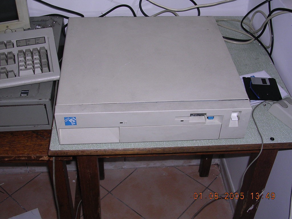
I don't have this unit anymore because during its operation it damaged itself from the bad power supply unit. After PSU fault, mainboard, hard disk and floppy disk drive have been electrically destroyed, probably by high voltage. I still have its mainboard, but I don't have casing anymore.
[Update 2022]: Thanks to some spare parts, I have resurrected the mainboard and I supply more details about pinouts and using generic components for it.
Expansion of this computer can be made using 72-pin SIMMs, but these modules are proprietary. If you have luck, some old SIMMs for normal 486 mainboards will work, but by the cost of BIOS errors on startup and slowing the computer a bit.
| Contents: | Starting, usage | Mainboard | Floppy | Links |
Starting
PS/1, if it has nowhere to boot from, may jump to on-ROM BASIC. In other cases it will boot floppy or hard disk. BIOS messages are usually not in English, but as code numbers. Code numbers can be checked here.
Boot disk (also contains diagnostic disk). If configuration has to be introduced, it must be done booting this disk. Remember that "Advanced diagnostic disk (ps1diag3.exe or disk image) may work, but may incorrectly set boot order to network device as the second.
Now about the boot disk: If there is an RTC error, I found that date not initialized using this disk is considered not set at all. So the first RTC set after battery replacement must be done using the disk. Additionally, after replacing RTC battery configuration should be re-done, and after saving it and rebooting, a boot device priority must be set. Without setting the boot device priority, the computer may try to boot from network instead of hard drive, even if it was configured otherwise. If right after POST it crashes displaying random number/characters on the screen it may be a failed network boot.
This boot disk can be found (as 2123strt.exe) on many PCBBS mirrors. However in these mirrors one thing has been skipped: Files index. It was constantly updated, so it doesn't contain index of /ps1/ folder. This folder was absent in IBM side some time, while mirrors preserved it. The result is that files in ps1 folder may not be indexed in allfiles.txt in your PCBBS mirror.
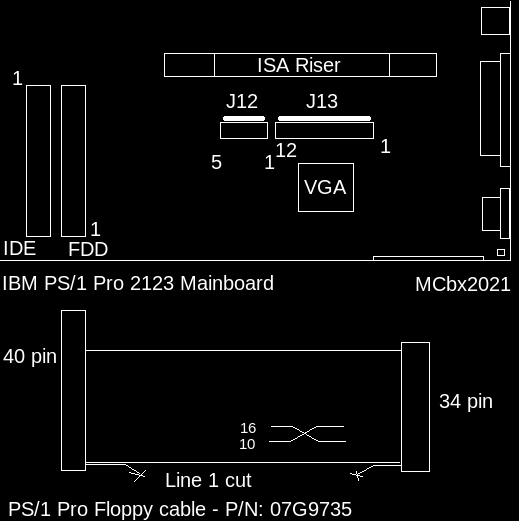
Mainboard and pinouts
Here are the most important pinouts. Moifying AT or even some ATX power supply units is totally possible:
|
The power supply pinout in my board is following:
|
|
||||||||||||||||||||||||||||||||||||||
Floppy drive
Want to use PC drive in PS/1? Now things become more complicated.
The
original tutorial is for another computer which does more simple
checks, but it is worth looking.
All information about IBM's drives is from
PS/2 Floppy Technical Reference.
The original tutorial is not much compatible with 2123. It looks like
PS/1 Pro does more checks than just checking the single bit of drive
parameters. After separating and properly connecting +5V and +12V, PS/1
may, depending on connecting pin 4 to ground:
- Throw misconfiguration (161) and diskette size (604) errors. While
trying to boot from floppy, first seeks look laggy and ends with read
failure (a few large seeks). It does not boot.
- Throw the same two errors, but not boot at all, making short seeking
sounds, like it does not see the disk in drive.
The difference will be, after booting from hard disk, that SC.EXE
configuration tool dosplays 1.44MB by default in one case, while in the
other it does not.
What is interesting, in one of these modes it may boot the diagnostic
disk properly, and then display the information that the floppy drive is
incompatible and should be replaced. In such case, configuration and
diagnostic program works surprisingly well, except of course floppy
drive.
So I decided to take my Mitsubishi original drive, look at the board and
measure the signals in vivo. Here are conclusions:
- The pinout is like "Enhanced 34-pin header interface", page 12 of PS/2
Floppy Technical Reference.
- The drive does not have PS/2's SECURITY feature, but PS/1's BIOS
checks for it by quickly flipping line 14. However, there is no response
from MEDIA TYPE lines.
- DATA RATE pins seem to be always in LOW-LOW configuration.
- Media ID 1 (17) is always low
- Media ID 0 (27) goes low if 720K disk is in drive AND the drive is
selected. This seems not to be used by DOS.
- ID1 (4) is virtually DRIVE SELECT. It must go low when DRIVE SELECT
goes low, but not be low when DRIVE SELECT is high.
- ID0 (9) goes exactly like ID1, except that it is open-collector.
- In some PC drives, some output lines are not pulled up.
So the tutorial:
SEPARATE means to cut the pin's tracks from the board. The pin should be
still solderable and it should not break signals for other pins.
PULL-UP means connect the 2K2 resistor between the pin and Vcc.
1. Bend pin 2 outwards (PS/1 seems not to use it - maybe in some edge
cases?).
2. Separate pin 33 (RATE0 signal is not used in PC drives, drive will
not process it).
3. Separate pin 14 to keep SECURITY attempts away from the drive.
4. Separate pin 27 (MEDIA ID0) and pull it up.
5. Separate pin 17 (MEDIA ID1) and ground it.
6. Separate pin 9 (DRIVE ID0) and connect it through the 1N4148 diode to
DSEL (12), cathode to DSEL. Now it goes low when DSEL goes low.
7. Separate pin 3 (+5V) and connect it to +5V input in the drive.
8. Separate pin 4 (DRIVE ID1) and jumper it to DSEL.
9. Separate pin 6 and, if 12V is needed, connect it to 12V input in the
drive.
10. Pull up lines: 34, 30, 28, 26.
11. Check ground pins! Did you really connected them all after this
cutting?
After auto-configuration from floppy drive, use "Fetaures" menu and configure the boot sequence properly as auto-configuration breaks it.
Here are some photos of the modification made in Mitsumi drive:
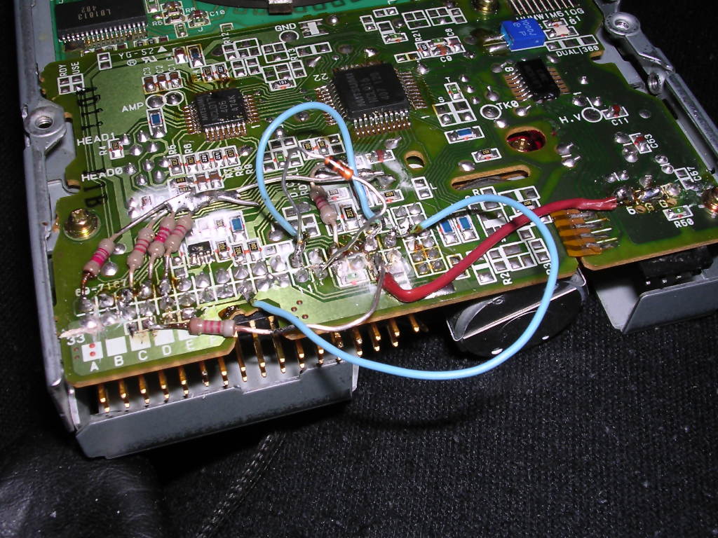 |
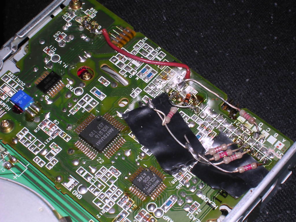 |
| Prototyping/testing approach | Final, flat version |
Links:
-
http://ps-2.kev009.com/pcpartnerinfo/ctstips/937e.htm - System
information
-
https://ps1stuff.wordpress.com/download/downloads-for-model-2123/ -
PS/1 stuff site with lots of information and downloads.
[Last update: 2022-05]